1-wire controller for Smart Home (Support for MQTT, UDP, Wwebsocket protocols)
version: 1.1 21.01.2020
The firmware was developed based on the previous project . As in the previous project, the main goal of the controller is autonomy and self-sufficiency for simple automation cases (without using expensive external controllers). Added web interface for device configuration. Technologically, the interface is a web-application that is stored in the extended memory of the ESP8266 device, this application interacts with the main application that runs in the device itself via the websocket protocol. This fact allows interact with the device in DIY mode, i.e. instead of a web application, there can be any user system. Data format which is used in the exchange - JSON. The controller can be used as a gateway to access devices on the 1-wire bus via protocols WebSocket and UDP, the data format remains the same. The controller can be used as a standalone control device, or as part of a more complex system such as OpenHab . The system may be several controllers in one segment of a Wi-Fi network, each controller is peer to peer, each controller receives information about all connected sensors and actuators from neighboring controllers.
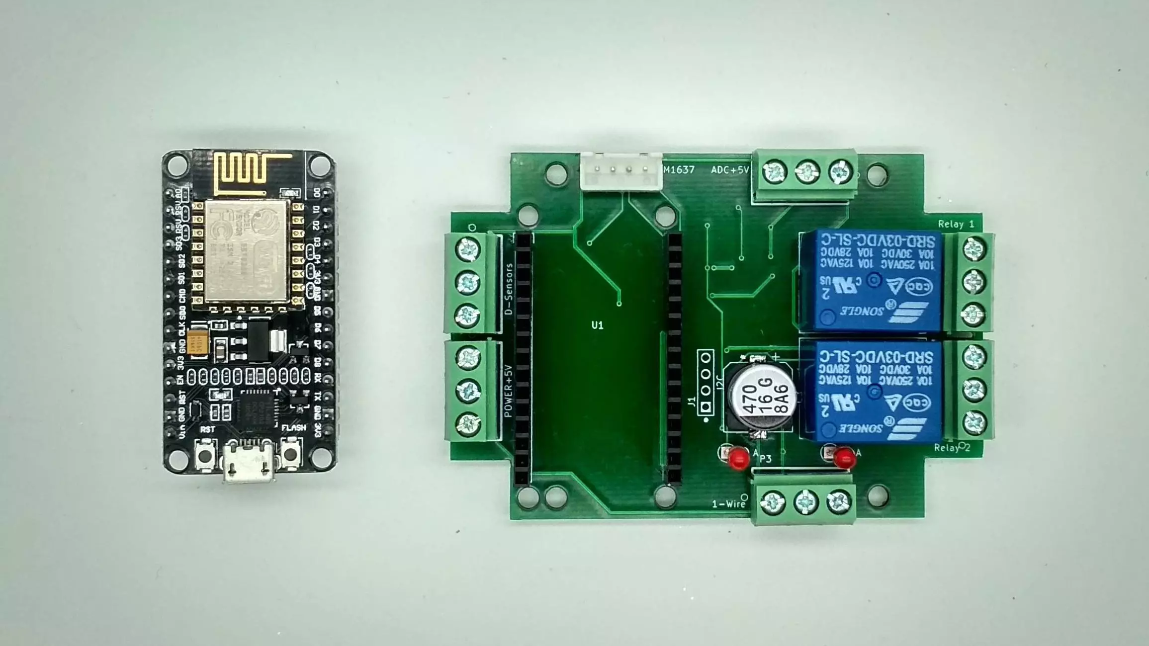
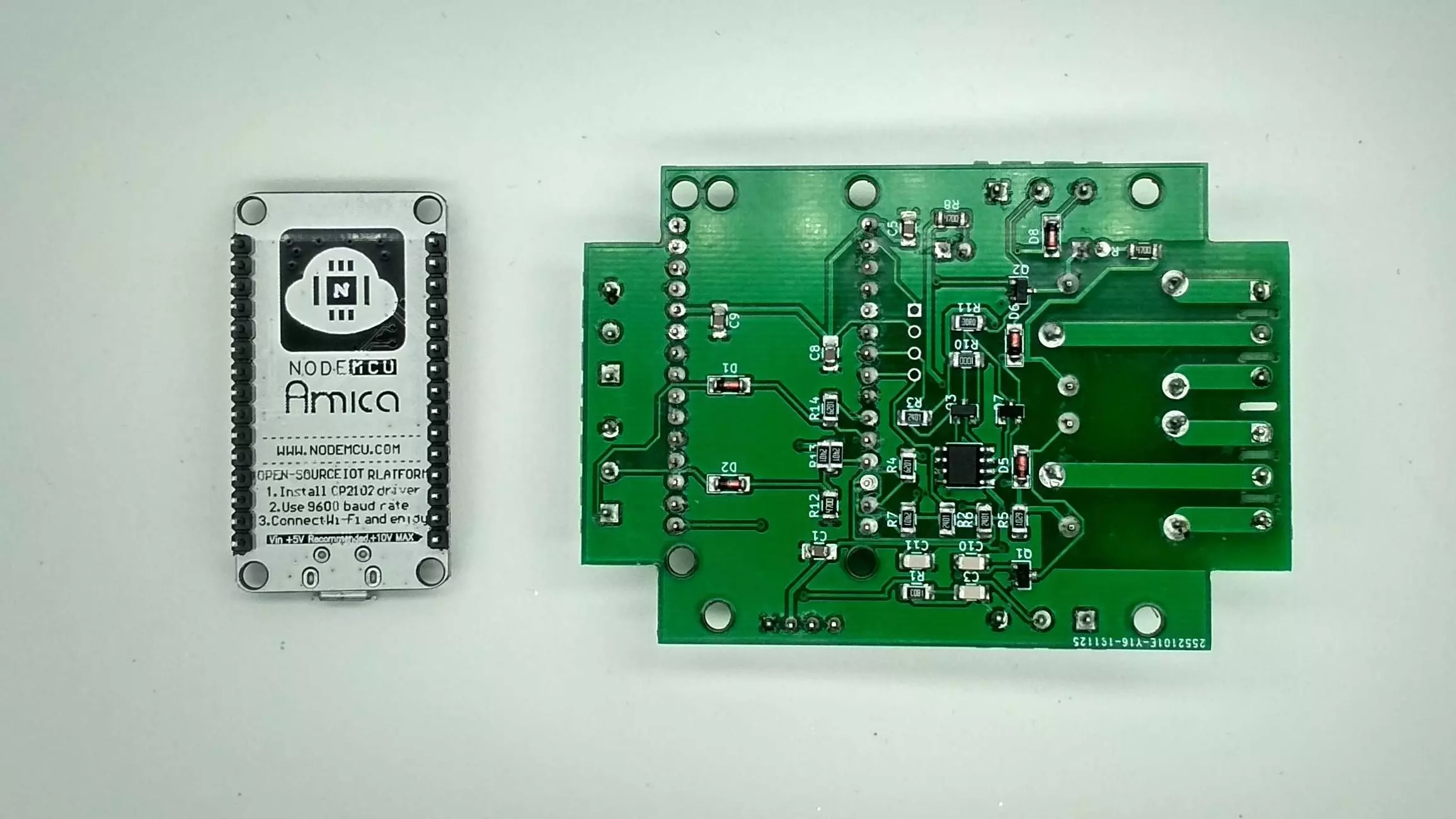
A device board has been developed for this project, which includes:
- Electromagnetic relay - 2 pcs;
- Didital sensor/counter - 2 pcs;
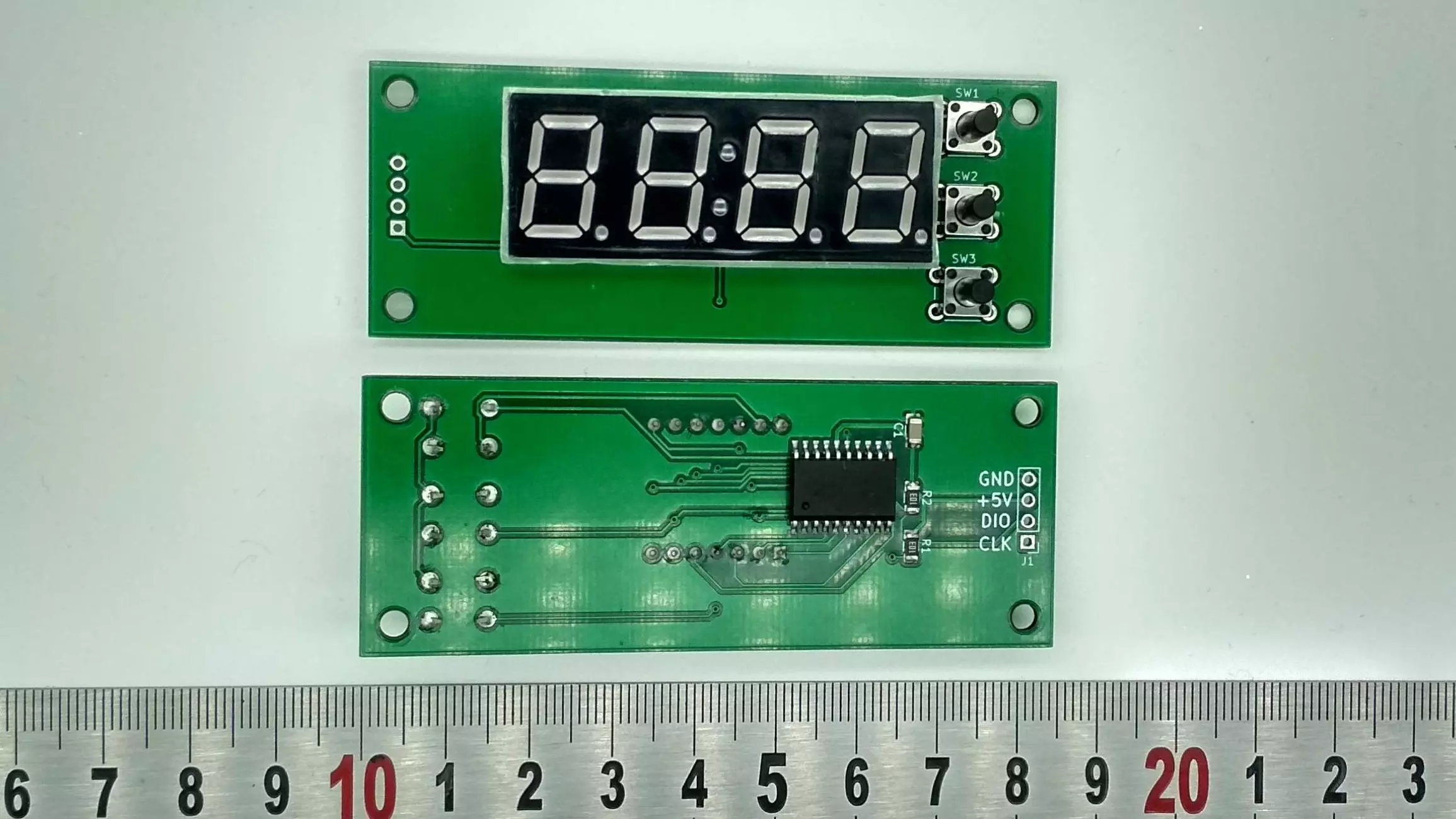
- LED segment display (4 segments) + three control buttons;
- voltmeter input up to 5 volts;
- 1-wire bus adapter (master) based on DS2482S-100 chip.
The device can be seen in the picture below:
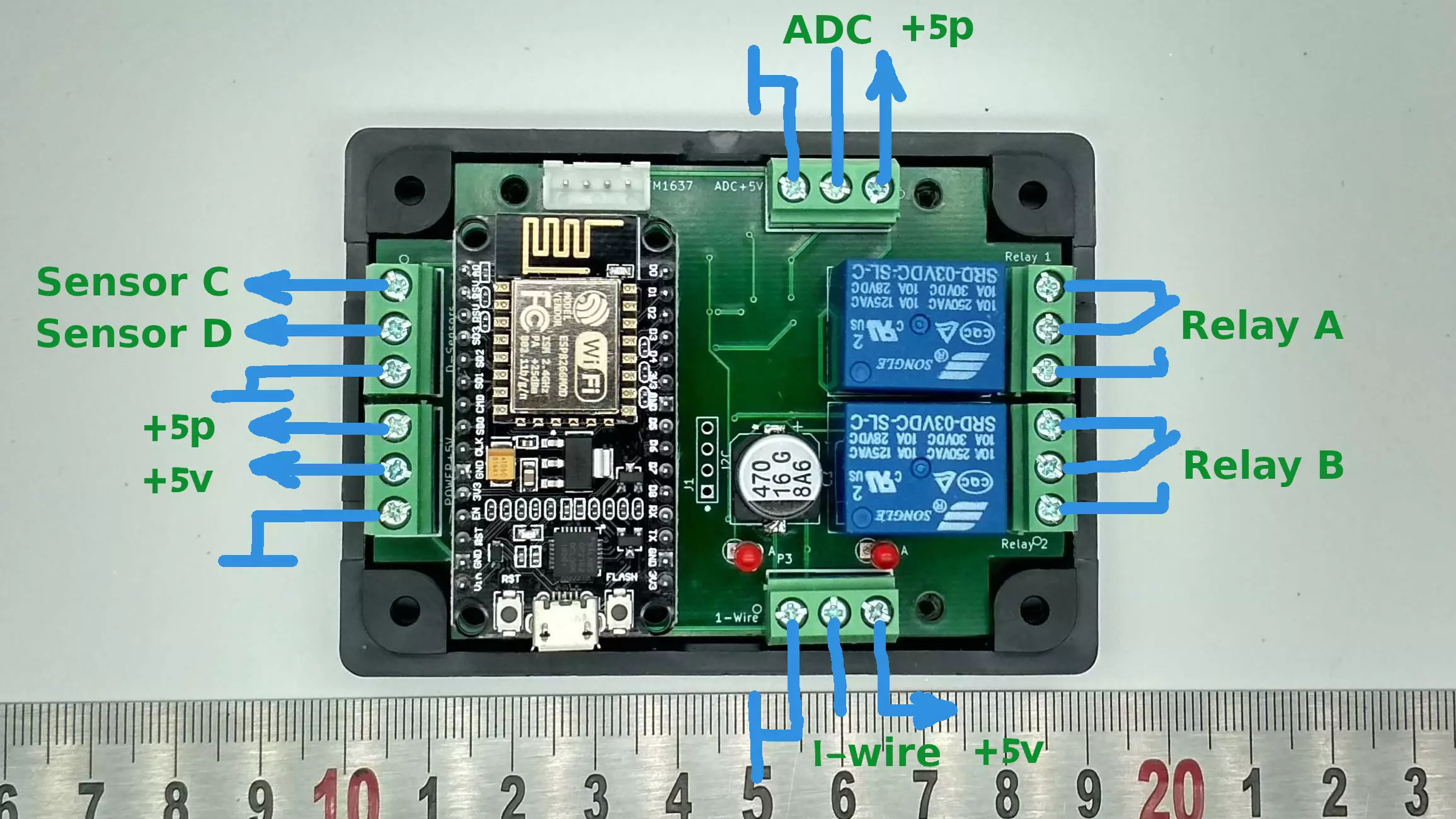
- Sensor C - input of the sensor / counter channel C, the normal state corresponds to a high (1) TTL level, the connected sensors must generate zero (0) pulses.
- Sensor D - input of the sensor / counter channel D.
- + 5V - from a power supply device.
- + 5P - power line to the uninterruptible power supply (UPS). If the UPS device is not available in the system, then the power outputs must be put together. The input Sensor D is combined with a voltage sensor. In the event of a power failure for more than 20 seconds, the controller will go into energy-saving operation mode (wi-fi will turn off), a voltage of +5 volts will only be supported at the bus output 1-wire and input Sensor C will work. After the appearance of voltage at the input + 5P, the controller will switch to normal operation.
- ADC - ADC input up to +5 volts.
- 1-wire - output of the 1-wire line.
The controller assumes the expansion of hardware functionality over the 1-wire bus, in the first stage (current) the following devices are supported:
- DS18B20 temperature sensor
- switch / sensor DS2413 (connecting sensors and actuators-relays)
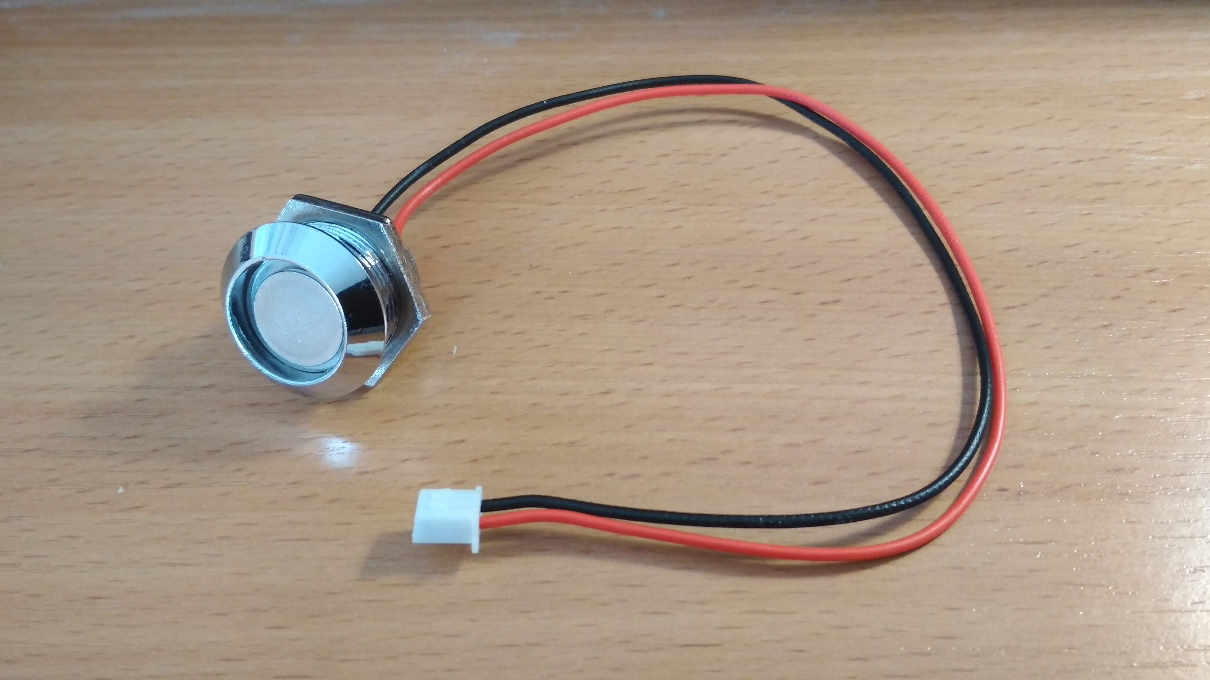
- iButton devices TM1990A
The maximum possible number of devices connected to the controller via the 1-wire bus is limited to 32.
Support is planned for other devices for the 1-wire bus and the development of the functionality of the firmware itself. Firmware includes auto update new versions via the Internet.
On the LED indicator, you can view the status of all connected sensors. When the temperature or the state of the sensor changes, The indicator will flash and show the number and value of this sensor.
Using the buttons, you can control the default relays set in the application or by selecting the desired relay module on the 1-wire bus with the middle button the top button turns on / off the channel relay A , and the bottom button turns on / off the channel relay B . In the device setup application You can select the relay module that the buttons will control by default.
When you turn on the device for the first time, it is in the AP mode of the WiFi access point so that the user can connect to it from your smartphone and make initial settings to connect to your home WiFi network. In the future, you can go to the device any Internet browser at an address of the form http://ow-XXXXXX.local , where XXXXXX is a unique device number.
UDP networking
To extend the system, it supports the interaction of controllers among themselves in one local Wi-Fi network. Values of connected sensors relays and sensors are transmitted over UDP using the broadcast method on port 7777 (the default, which can be changed). Each controller is equal in relation to each other. In the configuration application, you can see all the neighbors controllers. In the application, you can switch between controllers and configure them individually. In this way, individual monitoring / control zones can be automated and implemented. interaction between them, also without the participation of external controllers.
The firmware features can be seen in the demo application - esp.1vp.ru . ( The current version of the application is different from the demo! )
MQTT
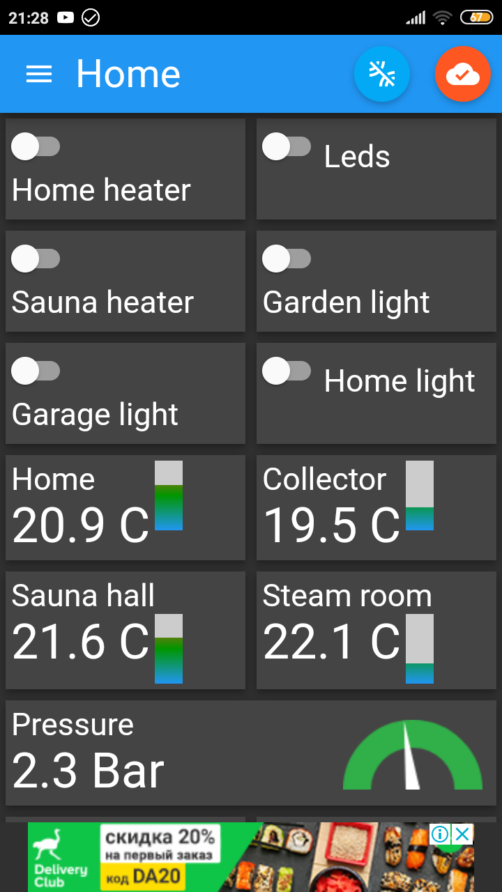
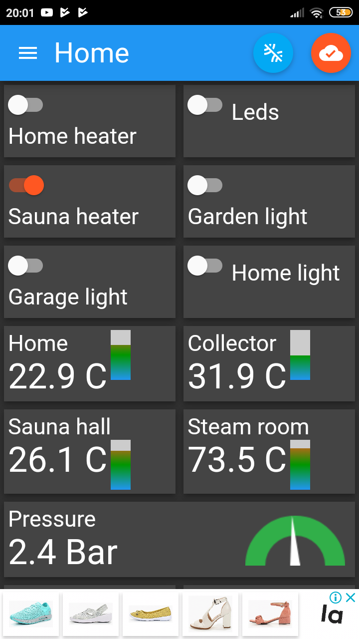
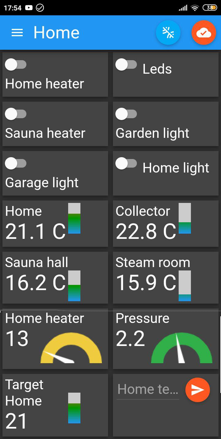
The mqtt-panel for the smartphone corresponds to this setup option from the demo application (screenshot below). Basically, the mqtt-panel is used for monitoring configured actuators in the application, but you can interfere with the automatic operation of the relay. If any relay remains If not configured, then it can be controlled only in manual mode using the mqtt panel or through DIY mode, using the websocket or UDP protocol. MQTT topics that are used by the controller can be seen in the web interface by setting it up by clicking on the "MQTT topics" icon for each from managed devices. Publish and Subscribe topics are for the controller, i.e. for the client (mqtt-panel) you need to configure the opposite: Subscribe and Publish. There is a command "sync", if you send it to the device in the root topic of the template: "/1vp.ru/esp8266/XXXXXX/" on any controller from several (neighbors), then devices will immediately respond with all topics. All controllers can be represented as in one MQTT panel so and in a few.
The mqtt-panel for the smartphone is configured to this option for setting up the application (screenshot below). Basically, the mqtt panel is used to monitor actuators configured in the application, but you can interfere with the automatic operation of the relay. If any relay remains not configured, it can only be controlled in manual mode using the mqtt panel or through the DIY mode, using the websocket protocol.
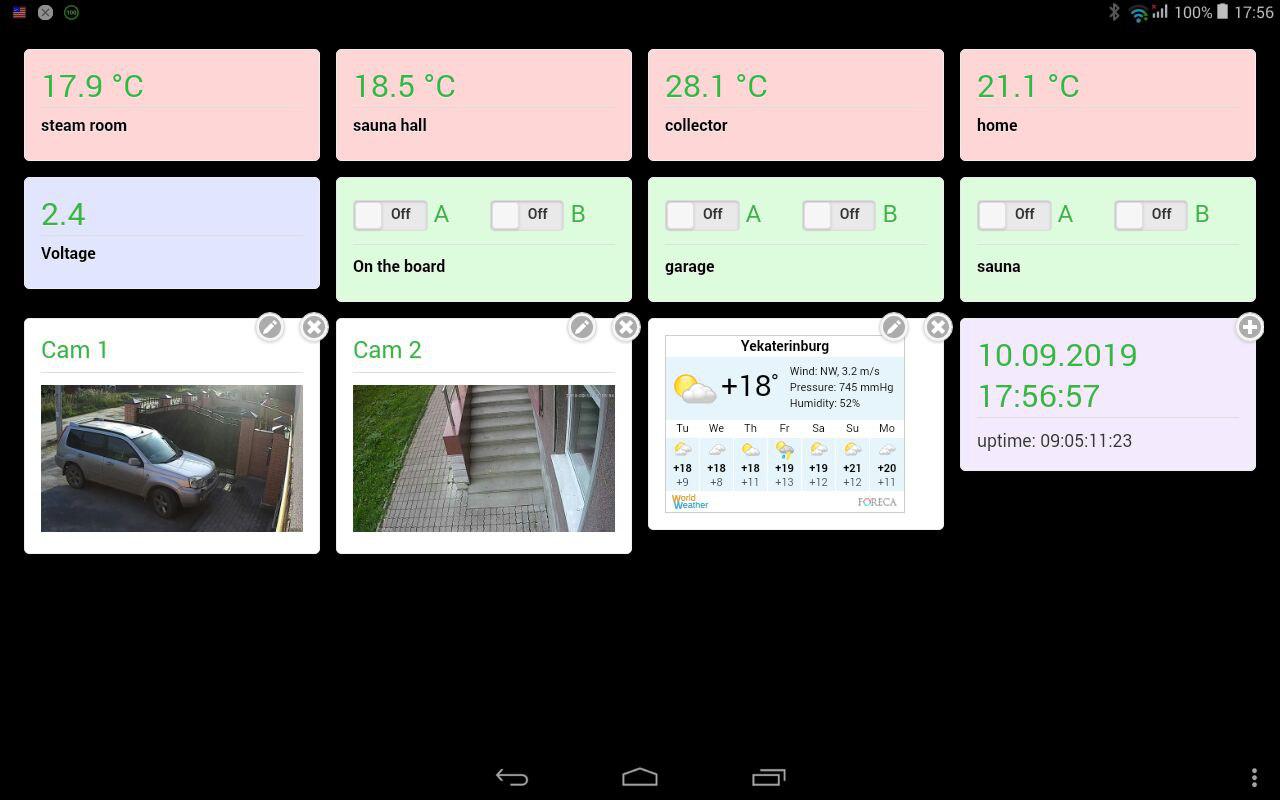
A web panel has been implemented that allows you to use any tablet as a smart home panel ( http://ow-XXXXXX.local/panel.html ). The panel can be saved on the main page of the tablet as an application. The panel allows you to place additional widgets, such as updated images with video surveillance cameras, weather widgets and more. The screenshot below in the picture:
The following is a description of the functions that can be configured for any relay (actuator) in the system.
Time relay
The time relay can be used to turn on any load in a certain period of time. To set turning on times and / or switching off relays, records are used in the format CRON , this format The task of the moments of time is chosen because of its universality and brevity of the record.
Time relay, Astro mode
For the case of turning on the lighting in the dark, this mode of operation is provided. The relay will be tied to an astronomical clock, to the moments of sunrise and sunset. At sunrise, the relay will turn off, and at sunset, turn on or vice versa, if you turn it on mode inversion option. You will need to set geographical coordinates your location and correction time in minutes relative to sunrise and sunset. The exact relay response time will be pay off: sunrise time + (plus) correction time and sunset time - (minus) correction time (offset). You can also set the on and / or off values for the normal "time relay" mode. Then the resulting state of the relay will be the result of two conditions for the logical operation "AND", i.e the time relay will be able to turn on according to astronomical time AND at given times.
Thermostat
Thermostat according to the temperature hysteresis algorithm with two temperature limits (normal and high). The normal border sets the temperature to be achieved by turning the load on and off, reaching the temperature + (plus) hysteresis temperature. Upper range designed for the case when you need to turn on the load again, when the upper temperature limit is reached, and turn it off when the temperature has dropped by the value of high hysteresis.
Thermostat (PID-controller)
This mode works according to the PID controller algorithm (proportional – integral – derivative controller). This algorithm provides more accurate temperature maintenance, in contrast to the temperature hysteresis algorithm.
In the picture you can observe the effect on various values of the parameters of the PID algorithm. By default, the following values are set: Kp = 2.0 Ki = 5.0 Kd = 1.0, the duration of one cycle was selected 960 seconds (16 minutes), due to the large inertia of the heating systems (values are adjustable). Parameters can be selected experimentally. The duration of the duty cycle (on state of the relay) is calculated by the algorithm. The settings include the minimum operating cycle time, as it makes no sense to turn on the heating engine or gas boiler for too a short time interval and a maximum time above which the relay will be constantly on, again, it makes no sense to turn off heating system for too short a time.
The thermostat module in the PID mode of the controller sends an mqtt-topic with the value of the percentage of the duration of the working cycle of the algorithm, which can be interpreted as a percentage of the power of the controlled device (a gas boiler, for example) at the current time.
In both thermostat modes, you can set time points and set the necessary target temperatures, also in the CRON format.
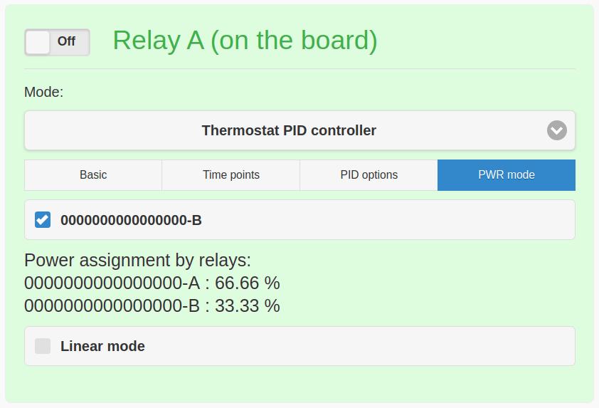
Implemented a power control mode with multiple relays. PWR-mode allows you to connect power consisting of several loads (e.g. heating shades). The percentage of connected minimum power and in increments depends on the number of connected relays for this mode. For example, two relays allow you to implement a step of 33% power and 4 gradations (0%, 33%, 66%, 100%). Three relays - 14.3% and 8 gradations and so on. The number of gradations is 2 in the degree of the number of relays. This mode means connecting loads of different capacities. It is also possible to connect loads of the same capacity (Linear mode).
Digital sensor
In this mode, the relay will turn on or off the load depending on the state of the digital sensor that is connected through the device on the 1-wire bus based on the DS2413 chip. If you just need to copy the status of a relay or turn on or off the load for a given time interval, depending from the state of another relay in the system.
Voltage sensor
The state of the relay turns on or off depending on the voltage level at the input of the sensor-voltmeter.
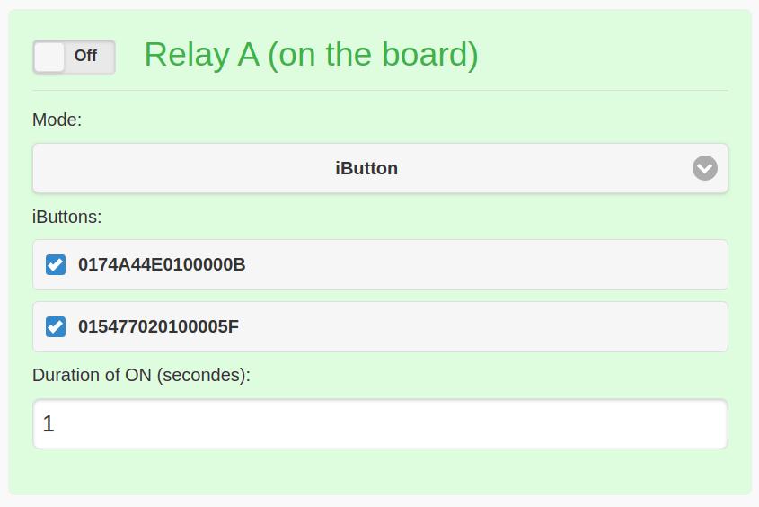
iButtons
The relay operates for the set time in seconds, if you attach a “tablet” key to the reader, which can be connected to the 1-wire bus. If the on-time is set to zero, then the relay will work as a trigger, the key will transfer the relay from one state to another. Any electronic keys compatible with DS1990A are suitable.